How is PCB manufactured?

December 5, 2022

The process of PCB manufacturing can be complex which involves a lot of steps. The PCB can be single layer, double or multi-layer based on their usage and applications and depending on this there can be multiple steps that are involved in creating the PCBs. Skipping any one step can prove costly to the final electronic product but when done properly it can fulfill the needs in an electronic application. 

What are the parts of PCB? 

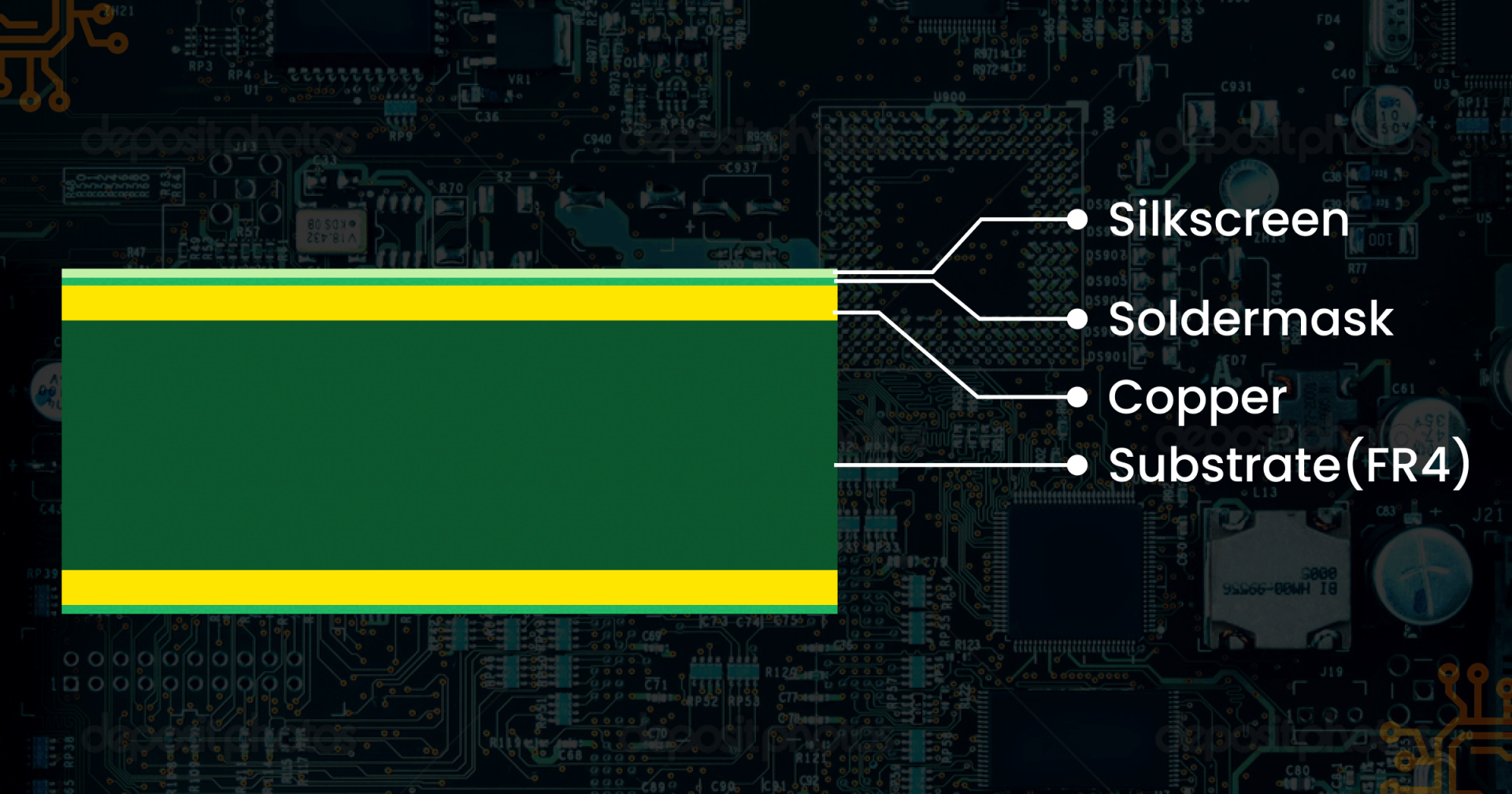
PCB has 4 main parts 

Substrate: Substrate act as the skeleton in the final product. They are mainly made of high-quality fiberglass, that provides the strength to the PCB and prevents breakage. 

Copper layer: Copper layer or coper foil can be used depending on the type of application and like metal, its primary use to carry electrical signals to and fro the PCB. 

Solder Mask: Solder mask is a layer of polymer on the top of copper to prevent any short circuit that happens if the copper comes in contact with the outer environment. 

Silkscreen: Silkscreen is given on the top of solder mask and is primarily for nomenclature details like number, logos, settings symbols, test points etc. 


How is the PCB manufactured? 

Now that we know the parts of PCB, its time to know more about the process of manufacturing the same. As told above, depending on the complexity and application the process steps differs and its mandatory to follow each and every step for the best results. 

  1. Designing the PCB- Like ever good things begins with a plan, so does manufacturing the PCB. To design PCB respective software's are used. Extended Gerber — also known as IX274X is one of the commonly used software for designing PCB. Once the design blueprint is finalized its cross checked to make sure there are no errors. The final design is sent to fabrication office, where it's given a second check called design for manufacture check, where it checks the parameters design and tolerance is met the needed threshold. 
  2. Design review and engineering- Checking the design for any flaws are error is the much-needed step to be done before jumpstarting the fabrication process and is done by an engineer who reports for any missing components or incorrect structures. 
  3. Printing the PCB design- Like any other design, PCB designs need to be printed and a special kind of printer called plotter printer. The final product looks like a film that’s printed on the board itself. 

The inside of the PCB uses 

Black Ink-For copper traces and circuits of PCB 

Clear Ink- For the nonconductive areas like fiberglass. 

The outside 

The outside of the PCB the color trend will be reversed. 

Each PCB layer & accompanying solder mask will get its own film. After the film is printed the sheets are lined up and a hole called registration hole is punched through them, which is used as a guide to align the films later on. 

  1. Printing the copper for inner layers- After the PCB is printed onto a piece of laminate material, a copper foil layer or copper coating layer. The copper is then prebonded to the same piece of laminate, the copper is etched then to reveal the blue print. Laminate is covered by photo sensitive material called resist which hardens when exposed to ultraviolet light and the resist helps to get a match between photos of blue print and what's to be printed to the photoresist. 

     Once the resist and laminate are lined up using the registration hole they receive a blast of UV light, the light passes through the translucent material which helps to harden the photoresist. The black ink doesn’t prevent the light from getting into areas that shouldn’t be hardened. 

After the board has been prepared its washed with alkaline solution to remove any photoresists and the board is pressure washed to remove anything left on the surface of the board and left to dry. After drying the only resist should be on the top of copper. Finally, the technical looks over the PCB for any flaws or errors. 

  1. Etch the inner layers to remove the copper- Inner layer of the board need to have the extra layer to be removed. Etching covers the needed copper exposing the rest to a chemical and hence removing it. The amount of solvent used depends on the amount of copper used as for large applications the copper used will be more. 
  2. Layer alignment- After each layer of the PCB has been cleaned its ready for alignment and optical inspection. The holes are used to align the sheets together. To align the layers, a technician places in a special type of punching material called optical punch. Optical punch drives a pin through the holes to line up the layers of PCB. 
  3. Automated optical inspection- Once the step 6 is completed the optical inspection is carried out so that there are no errors being there. On the completion of optical inspection an AOI machine inspection is carried out to check for any short circuits, extra copper which should be removed before further. 
  4. Laminating the PCB layer- Once the the inspection is done, the layers should be fused and the lamination is done in basically two steps- the laying step and lamination step. 

      Once the outer and inner layers are ready, they should be sandwiched together to get the final picture. For this a special type of table is used on which each layer is secured with a pin and special metal clamps are used. A layer of pre-impregnated epoxy resin is placed followed by a layer of substrate then a copper foil layer. The copper layer is followed by many layers of pre-impregnated resin, finished off with a copper plate called press plate. 

Pins are pressed through the sheet to ensure that the layers stay intact. After the copper plate is placed next step is to the stack to be pressed which is done using a mechanical press. The stack is then taken to the laminating press where heat and pressure is applied to the stack. Heat causes the resin to melt and pressure applied causes the layers to press and fuse together. After the layers are pressed together the top press plates & pins are removed. 

  1. Drilling- Holes are drilled using the extended Gerber design as the reference and is done using computer guided drill. X ray machine is used to drill the holes, then the registration holes are drilled so that PCB stack layers can be secured. 

10. PCB plating- Plating uses different types of chemicals to fuse the layers together. The process called as bathing is carried out where the PCB layers are bathed in a series of chemicals. In bathing process, the panel is coated with a micron thick layer of copper. 

11. Outer Layer Imaging- In step 4, a photo resist was applied to the PCB panel, similarly here also a photoresist coating needs to be applied. But this time only the outer layer needs to be coated as they are the ones to be imaged and plating is done using tin to secure the copper of outside layer. 

12.Outer layer etching- The outer tin covering act as a covering for the copper layer from etching. Any unwanted copper is removed using the solvent as before. Previously for inner layer etching dark ink is used for conductive areas and light ink for non-conductive areas, these ink are reversed for outer layers. The non-conductive area has dark ink and conductive area has light ink. The light ink allows the tin plating to cover and protect the copper. 

13. Outer layer AOI- As done with the inner layer, the outer layer too must go through the set of inspections. Any unwanted coating is checked along with the design specifications. It will only go through the next steps if all the conditions needed to perfect the design are met. 

14. Solder mask application- Once the panel is clean, they will now go through solder mask application. Each panel has epoxy resin and solder mask fil covering. UV light is used to check where the solder mask need to be removed. Once the unwanted solder mask is removed, its taken to an oven to cure the mask, this mask provides extra protection for the copper from corrosion and oxidation. 

15.Silk screen application- All the vital data should be written on the board itself for better convenience and is also called legend printing. The data to be given include 

  •  Manufacturer data & logo 
  • Company ID & Specifications 
  • Warnings 
  • Pin locators & similar identifications. 
  • Part numbers 

 Using an inkjet printer the information is printed on the board and is proceeded for further steps. 

16.Finishing the PCB- Finishing requires to be done using conductive material like below ones 

  • Electroless nickel electroless palladium immersion gold- High solder strength, prevents corrosion, require proper maintenance & less cost effective. 
  • Organic Solderability Preservative- Cost effective, short shelf life, RoHS complaint. 
  • Immersion tin- RoHS compliant, tight tolerance on holes, useful for press fit applications. 
  • Lead free HASL- Long lasting, reworkable, contains lead, not RoHS compliant, cost effective. 
  • Electroless nickel immersion gold- Expensive, RoHS compliant, long shelf life. 
  • Hard Gold- Long shelf life, durable, lead free, expensive. 
  • Immersion silver- lead free, the finish can oxidise and tarnish, low signal. 

17. Electrical reliability test- Once the coating and curing is done, different electrical tests are conducted to check the reliability. Electrical testing should adhere to standards of IPC-9252. One test is circuit continuity test and other one is isolation test. The continuity test checks for any circuit disconnections. The isolation test checks for isolation values of PCB parts to check for any shorts. 

18.Profiling & route out- profiling will identify shape & size of the PCBs. Routing out or scoring allows the easier separation of boards. A router or CNC machine creates several small pieces along the edge of the board so that it can quickly break off without damage. 

19.Quality check and inspection- PCB again undergoes final inspection. It checks for whether the hole size are matching for all layers, the board have its specific dimensions, clean and dust free, not having sharp edges. 

20.Packaging & Delivery- Packaging involves material that seals the board from dust and foreign particles. The sealed boards are then put in containers that protect them damage from shipping. 

PCB manufacturing is no piece of cake, it involves a lot of articulate steps that need to be followed. We design our processes to accommodate all type of printed circuit board assembly, whether they are thin, thick, or flexible, small or large, single sided or double sided, single layered or multi-layered or even mixed technology. With our connections to the large PCB manufacturers in the Far East we can provide you with PCB assemblies that use the best quality PCB’s at the lowest cost New Paragraph


By Swetha Parvathy March 21, 2025
The Evolution of Automotive Electronics: Trends and Advancements The automotive industry has undergone significant transformations over the years, and one of the key drivers of this change has been the rapid evolution of automotive electronics. From simple radio systems to complex advanced driver-assistance systems (ADAS), electronics have become an integral part of modern vehicles. In this blog, we'll explore the trends and advancements that are shaping the future of automotive electronics. The Early Days of Automotive Electronics The first electronic systems in vehicles were introduced in the 1950s and 1960s, with the advent of radio systems, heaters, and basic ignition systems. These early systems were relatively simple and consisted of a few discrete components. The Rise of Microcontrollers and Engine Control Units (ECUs) The 1970s and 1980s saw the introduction of microcontrollers and ECUs, which revolutionized the automotive electronics landscape. Microcontrollers enabled the development of more complex systems, such as anti-lock braking systems (ABS) and traction control systems (TCS). The Advent of Advanced Driver-Assistance Systems (ADAS) The 1990s and 2000s witnessed the emergence of ADAS, which rely heavily on advanced electronics and sensors. Systems like adaptive cruise control, lane departure warning, and automatic emergency braking have become increasingly common in modern vehicles. Current Trends and Advancements 1. Electrification and Autonomous Vehicles: The shift towards electric and autonomous vehicles is driving the development of more advanced electronics, including high-performance computing platforms and sophisticated sensor systems. 2. Connectivity and IoT: The increasing demand for connected cars and IoT-enabled vehicles is driving the adoption of advanced wireless communication technologies, such as 5G and Wi-Fi. 3. Artificial Intelligence and Machine Learning: AI and ML are being increasingly used in automotive electronics to enable advanced features like predictive maintenance, driver monitoring, and personalized infotainment. 4. Cybersecurity: As vehicles become more connected and reliant on electronics, cybersecurity is becoming a major concern. Automotive manufacturers are investing heavily in developing robust cybersecurity measures to protect against hacking and other threats. Future Outlook The future of automotive electronics looks promising, with emerging trends like: 1. Vehicle-to-Everything (V2X) Communication: Enables vehicles to communicate with other vehicles, infrastructure, and pedestrians. 2. Augmented Reality and Virtual Reality: Enhances the driving experience with immersive and interactive displays. 3. Quantum Computing: Enables faster and more secure processing of complex data. In conclusion, the evolution of automotive electronics has been remarkable, and the future looks even more exciting. As technology continues to advance, we can expect to see even more innovative and sophisticated electronic systems in vehicles.
By Swetha Parvathy March 21, 2025
The body content of your post goes here. To edit this text, click on it and delete this default text and start typing your own or paste your own from a different source.
By Swetha Parvathy February 24, 2025
The Internet of Things (IoT) has revolutionized the way we live and work, connecting billions of devices and transforming industries. As we look to the future, it's clear that IoT will continue to play a major role in shaping our world. In this blog, we'll explore the top trends and predictions for the IoT industry over the next five years. Trend 1: Increased Adoption of Edge Computing Edge computing is a distributed computing paradigm that brings data processing closer to the source of the data, reducing latency and improving real-time decision-making. As IoT devices become more widespread, edge computing will become increasingly important for processing the vast amounts of data generated by these devices. Trend 2: Growing Importance of Artificial Intelligence (AI) and Machine Learning (ML) AI and ML will play a crucial role in the future of IoT, enabling devices to learn from their environment and make decisions autonomously. This will lead to increased efficiency, productivity, and innovation across various industries. Trend 3: Expansion of IoT into New Industries IoT is no longer limited to traditional industries like manufacturing and logistics. Over the next five years, we can expect to see IoT adoption in new industries such as: - Healthcare: IoT will enable remote patient monitoring, personalized medicine, and improved healthcare outcomes. - Agriculture: IoT will optimize crop yields, reduce waste, and improve supply chain efficiency. - Smart Cities: IoT will enable cities to become more efficient, sustainable, and livable. Trend 4: Increased Focus on Security and Privacy As IoT devices become more ubiquitous, security and privacy concerns will become increasingly important. We can expect to see a greater emphasis on secure-by-design principles, encryption, and secure data storage. Trend 5: Advancements in Wireless Communication Technologies Wireless communication technologies like 5G, Wi-Fi 6, and Bluetooth 5 will continue to evolve, enabling faster data transfer rates, lower latency, and greater connectivity. Prediction 1: IoT Devices Will Exceed 50 Billion by 2025 The number of IoT devices is expected to grow exponentially over the next five years, driven by increasing demand for smart home devices, wearables, and industrial IoT solutions. Prediction 2: IoT Will Drive Business Model Innovation IoT will enable new business models, such as product-as-a-service, data-driven services, and subscription-based models. Companies that adopt IoT will need to rethink their business strategies to remain competitive. Prediction 3: IoT Will Improve Sustainability and Reduce Carbon Footprint IoT will play a critical role in reducing carbon emissions and improving sustainability. By optimizing energy consumption, reducing waste, and improving supply chain efficiency, IoT will help companies meet their sustainability goals. Conclusion The future of IoT is exciting and rapidly evolving. Over the next five years, we can expect to see increased adoption of edge computing, AI, and ML, as well as expansion into new industries. As IoT continues to transform industries and improve our lives, it's essential to stay informed about the latest trends and predictions. By doing so, we can unlock the full potential of IoT and create a more connected, efficient, and sustainable world.
By Swetha Parvathy February 13, 2025
Inductors are a crucial component in electronic circuits, playing a vital role in filtering, impedance matching, and energy storage. With so many types of inductors available, selecting the right one for your circuit can be a daunting task. In this guide, we'll walk you through the key factors to consider when choosing an inductor, helping you make an informed decision for your design. Understanding Inductor Types Before diving into the selection process, it's essential to understand the different types of inductors available: 1. Air Core Inductors: These inductors have no magnetic core and are often used in high-frequency applications. 2. Ferrite Core Inductors: Ferrite core inductors use a magnetic core to increase inductance and are commonly used in power supplies and filters. 3. Iron Core Inductors: Iron core inductors use a magnetic core made of iron and are often used in high-current applications. 4. Toroidal Inductors: Toroidal inductors have a doughnut-shaped core and are used in applications where a high inductance value is required. 5. Chip Inductors: Chip inductors are surface-mount devices that offer high inductance values in a small package. Key Factors to Consider When selecting an inductor, consider the following factors: 1. Inductance Value: Choose an inductor with the correct inductance value for your application. Inductance values range from a few nanohenries (nH) to several henries (H). 2. Current Rating: Select an inductor that can handle the maximum current required by your circuit. 3. Frequency Range: Choose an inductor that operates within the frequency range of your application. 4. DC Resistance: Consider the DC resistance of the inductor, as it can affect the overall efficiency of your circuit. 5. Physical Size: Select an inductor that fits within the physical constraints of your design. 6. Temperature Range: Choose an inductor that operates within the temperature range of your application. 7. Cost and Availability: Consider the cost and availability of the inductor, as well as any potential lead-time issues. Additional Considerations 1. Saturation Current: Be aware of the saturation current of the inductor, as it can affect the overall performance of your circuit. 2. Shielding: Consider the shielding requirements of your inductor, as it can affect the overall electromagnetic compatibility (EMC) of your design. 3. Mounting: Select an inductor with a suitable mounting option, such as through-hole or surface-mount. Conclusion Choosing the right inductor for your circuit requires careful consideration of several factors. By understanding the different types of inductors available and considering key factors such as inductance value, current rating, and frequency range, you can select the optimal inductor for your design. Remember to also consider additional factors such as saturation current, shielding, and mounting to ensure the best possible performance. Recommended Products - Ferrite Core Inductors: Our ferrite core inductors offer high inductance values and are suitable for a wide range of applications. - Chip Inductors: Our chip inductors are surface-mount devices that offer high inductance values in a small package. - Toroidal Inductors: Our toroidal inductors have a doughnut-shaped core and are used in applications where a high inductance value is required.
By Swetha Parvathy January 29, 2025
Artificial intelligence (AI) has come a long way since its inception, transforming industries and revolutionizing the way we live and work. As we step into a new decade, it's exciting to think about what the future holds for AI. In this blog, we'll explore the latest trends and predictions that will shape the future of artificial intelligence. Trend 1: Increased Adoption of Edge AI Edge AI refers to the deployment of AI algorithms on edge devices, such as smartphones, smart home devices, and autonomous vehicles. This trend is driven by the need for faster processing, reduced latency, and improved security. As edge AI continues to advance, we can expect to see more intelligent devices that can operate independently, without relying on cloud connectivity. Trend 2: Rise of Explainable AI (XAI) As AI becomes more pervasive, there's a growing need to understand how AI algorithms make decisions. Explainable AI (XAI) is a subfield of AI that focuses on developing techniques to interpret and explain AI-driven decisions. XAI will become increasingly important in high-stakes applications, such as healthcare, finance, and law. Trend 3: Autonomous Systems Autonomous systems, such as self-driving cars, drones, and robots, will continue to advance in the coming years. These systems will rely on sophisticated AI algorithms to navigate complex environments, make decisions in real-time, and interact with humans. Trend 4: Human-AI Collaboration As AI becomes more integrated into our daily lives, there's a growing recognition of the need for human-AI collaboration. This trend is driven by the realization that AI is not a replacement for human intelligence, but rather a complement to it. We can expect to see more AI systems designed to collaborate with humans, augmenting our abilities and enhancing our productivity. Trend 5: AI for Social Good AI has the potential to drive significant social impact, from improving healthcare outcomes to reducing climate change. As AI continues to advance, we can expect to see more applications of AI for social good, including AI-powered disaster response systems, AI-driven medical research, and AI-based environmental monitoring systems. Predictions for the Future of AI 1. AI will become ubiquitous: AI will become an integral part of our daily lives, from smart homes to autonomous vehicles. 2. AI will create new job opportunities: While AI may automate some jobs, it will also create new job opportunities in fields such as AI development, deployment, and maintenance. 3. AI will drive significant social impact: AI will be used to drive significant social impact, from improving healthcare outcomes to reducing climate change. 4. AI will raise important ethical questions: As AI becomes more pervasive, we'll need to address important ethical questions, such as bias in AI decision-making and the potential for AI to exacerbate social inequalities. Conclusion The future of artificial intelligence is exciting and rapidly evolving. As we look ahead to the next decade, it's clear that AI will play an increasingly important role in shaping our world. From edge AI to human-AI collaboration, these trends and predictions offer a glimpse into the future of AI and its potential to drive significant social impact.
By Swetha Parvathy January 22, 2025
Industrial settings, such as warehouses, manufacturing plants, and construction sites, require reliable and efficient lighting to ensure safety, productivity, and energy efficiency. Traditional lighting options, such as fluorescent and high-intensity discharge (HID) lamps, have been widely used in industrial settings, but they have several drawbacks. LED lighting, on the other hand, offers numerous benefits that make it an attractive alternative for industrial settings. Benefits of LED Lighting in Industrial Settings 1. Energy Efficiency: LED lighting is significantly more energy-efficient than traditional lighting options. LEDs use up to 90% less energy than HIDs and 50% less energy than fluorescent lamps. This can lead to substantial cost savings on energy bills. 2. Longer Lifespan: LEDs have a much longer lifespan than traditional lighting options. They can last up to 50,000 hours or more, compared to 10,000 to 20,000 hours for HIDs and 8,000 to 10,000 hours for fluorescent lamps. This means fewer replacements and reduced maintenance costs. 3. Improved Safety: LEDs are free from toxic chemicals like mercury and lead, which are found in some traditional lighting options. They also produce minimal heat, reducing the risk of burns and fires. 4. Increased Productivity: LEDs can improve visibility and reduce eye strain, leading to increased productivity and reduced errors. They can also be designed to provide specific lighting levels and colors to enhance task performance. 5. Design Flexibility: LEDs offer design flexibility, allowing for a wide range of lighting options, including color temperature, beam angle, and dimming capabilities. 6. Reduced Maintenance: LEDs require minimal maintenance, as they are resistant to shock, vibration, and extreme temperatures. 7. Environmental Benefits: LEDs are an environmentally friendly option, as they are free from toxic chemicals and can be recycled. Industrial LED Lighting Applications 1. Warehouse Lighting: LEDs can provide high-bay lighting for warehouses, reducing energy consumption and improving visibility. 2. Manufacturing Lighting: LEDs can provide task lighting for manufacturing applications, improving productivity and reducing errors. 3. Construction Lighting: LEDs can provide temporary lighting for construction sites, reducing energy consumption and improving safety. 4. Parking Garage Lighting: LEDs can provide energy-efficient lighting for parking garages, improving visibility and reducing energy consumption. Conclusion LED lighting offers numerous benefits for industrial settings, including energy efficiency, longer lifespan, improved safety, increased productivity, design flexibility, reduced maintenance, and environmental benefits. By switching to LED lighting, industrial facilities can reduce energy consumption, improve visibility, and enhance productivity, while also reducing their environmental impact.
By Swetha Parvathy January 6, 2025
The rapid advancement of electronic devices has led to a significant increase in heat generation, making thermal management a critical aspect of electronics design. As devices become smaller, faster, and more powerful, managing heat effectively is crucial to ensure reliability, performance, and safety. In this blog post, we'll explore the latest trends and best practices in thermal management for electronics, highlighting key strategies and technologies to help you optimize thermal performance and reduce heat-related failures. The Importance of Thermal Management Thermal management is essential in electronics design for several reasons: 1. Reliability: Excessive heat can lead to component failure, reducing the overall reliability of the device. 2. Performance: High temperatures can slow down device performance, affecting processing speed, memory, and overall functionality. 3. Safety: Overheating can cause electrical shocks, fires, or explosions, posing a significant risk to users and surrounding environments. Trends in Thermal Management Several trends are shaping the thermal management landscape: 1. Increased Use of Advanced Materials: New materials like graphene, nanomaterials, and phase-change materials are being explored for their exceptional thermal properties. 2. Integration of Thermal Management into System Design: Thermal management is becoming an integral part of system design, rather than an afterthought. 3. Growing Adoption of Liquid Cooling: Liquid cooling is gaining popularity, particularly in high-performance applications like data centers, gaming PCs, and electric vehicles. 4. Development of Smart Thermal Management Systems: Advanced sensors, algorithms, and control systems are being developed to optimize thermal management in real-time. Best Practices for Thermal Management To ensure effective thermal management, follow these best practices: 1. Conduct Thorough Thermal Analysis: Perform thermal simulations and testing to identify potential hotspots and optimize thermal design. 2. Select Suitable Thermal Interface Materials: Choose materials with high thermal conductivity and suitable mechanical properties. 3. Optimize Heat Sink Design: Design heat sinks with optimal geometry, material, and fin arrangement to maximize heat transfer. 4. Implement Active Cooling Solutions: Use fans, blowers, or liquid cooling systems to actively remove heat from high-temperature components. 5. Monitor and Control Temperature: Implement temperature sensors and control systems to monitor and regulate temperature in real-time. Conclusion Thermal management is a critical aspect of electronics design, and its importance will only continue to grow as devices become more complex and powerful. By staying up-to-date with the latest trends and best practices, you can ensure your devices operate reliably, efficiently, and safely.
By Swetha Parvathy December 31, 2024
Quartz crystal oscillators (QCOs) have been a crucial component in electronic devices for decades, providing a stable clock signal that enables precise timing and frequency control. From their humble beginnings to the present day, QCOs have undergone significant transformations, driven by advances in materials science, manufacturing techniques, and market demands. In this article, we'll delve into the evolution of quartz crystal oscillators, exploring their past, present, and future. The Early Days: 1920s-1950s The concept of using quartz crystals for frequency control dates back to the 1920s. Researchers discovered that quartz crystals, when excited by an electric current, could produce a stable frequency signal. This phenomenon, known as piezoelectricity, laid the foundation for the development of QCOs. In the 1950s, the first quartz crystal oscillators were introduced, primarily used in military and telecommunications applications. These early QCOs were relatively large, expensive, and prone to frequency drift. The Golden Age: 1960s-1980s The 1960s marked the beginning of the golden age for QCOs. Advances in quartz crystal growth, cutting, and polishing techniques led to improved frequency stability and reduced production costs. This, in turn, enabled the widespread adoption of QCOs in various industries, including consumer electronics, aerospace, and automotive. During this period, QCOs underwent significant design and packaging innovations, such as the introduction of metal packages, surface-mount technology, and voltage-controlled oscillators (VCOs). Modern Era: 1990s-Present The 1990s saw the emergence of new technologies that further transformed the QCO landscape. Some notable developments include: 1. AT-Cut Quartz Crystals: The introduction of AT-cut quartz crystals, which offered improved frequency stability and reduced aging effects. 2. Surface-Acoustic Wave (SAW) Technology: SAW technology enabled the creation of smaller, more stable QCOs with improved frequency accuracy. 3. MEMS-Based QCOs: The development of microelectromechanical systems (MEMS)-based QCOs, which offered enhanced performance, reduced size, and lower power consumption. Today, QCOs are ubiquitous in modern electronics, found in applications ranging from smartphones and laptops to medical devices and industrial control systems. Future Outlook As technology continues to advance, QCOs will likely undergo further transformations. Some potential trends and developments on the horizon include: 1. Increased Integration: Further integration of QCOs with other components, such as microcontrollers and sensors, to create more compact and efficient systems. 2. Advanced Materials: The exploration of new materials and technologies, such as graphene and nanomaterials, to improve QCO performance and reduce size. 3. Wireless and Wearable Applications: The growing demand for wireless and wearable devices will drive the development of smaller, more power-efficient QCOs. 4. IoT and 5G: The proliferation of IoT devices and 5G networks will require QCOs with improved frequency stability, accuracy, and reliability. In conclusion, the evolution of quartz crystal oscillators has been a remarkable journey, marked by significant technological advancements and innovations. As we look to the future, it's clear that QCOs will continue to play a vital role in shaping the electronics landscape. About US Electronics US Electronics is a leading provider of quartz crystal oscillators and other electronic components. With a commitment to quality, innovation, and customer satisfaction, we supply QCOs to a wide range of industries and applications. Contact us today to learn more about our products and services.
By Swetha Parvathy November 13, 2024
Introduction The power supply industry is rapidly evolving, driven by advancements in technology, growing demand for efficient energy solutions, and increasing applications in emerging markets. As we look to the future, it's essential to explore the trends and innovations shaping the power supply landscape. Trends: 1. Increased Efficiency: Next-generation power supplies will prioritize high efficiency, reducing energy waste and minimizing environmental impact. 2. Digital Power Supplies: Digital control and monitoring will become more prevalent, enabling real-time optimization and improved reliability. 3. Wide-Bandgap Semiconductors: Silicon carbide (SiC) and gallium nitride (GaN) semiconductors will revolutionize power supply design, offering higher efficiency and power density. 4. Modular and Configurable Designs: Modular power supplies will gain popularity, allowing for customized solutions and simplified upgrades. 5. Wireless Power Transfer: Wireless charging technology will expand beyond consumer devices to industrial and medical applications. Innovations: 1. GaNFETs and SiC MOSFETs : New semiconductor materials enabling faster switching, higher efficiency, and reduced heat dissipation. 2. Resonant and Soft-Switching Technologies : Minimizing switching losses and electromagnetic interference (EMI). 3. Artificial Intelligence (AI) and Machine Learning (ML) : Optimizing power supply performance, predicting maintenance, and enhancing reliability. 4. 3D Printing and Additive Manufacturing : Streamlining production, reducing material waste, and enabling complex geometries. 5. Energy Harvesting and Regeneration : Capturing and reusing energy from environmental sources or system waste. Emerging Applications: 1. Electric Vehicles (EVs) and Charging Infrastructure 2. Renewable Energy Systems and Smart Grids 3. Industrial Automation and IoT Devices 4. Medical Devices and Healthcare Technology 5. Aerospace and Defense Systems Conclusion The future of power supply technology promises significant advancements in efficiency, reliability, and innovation. As the industry continues to evolve, US-Electronics remains committed to delivering cutting-edge power supply solutions that meet the growing demands of our customers. Call-to-Action Stay ahead of the curve with US-Electronics' expertise in power supply design and manufacturing. Contact us to discuss your custom power supply needs and learn more about our innovative solutions.
By Swetha Parvathy June 10, 2024
Understanding electronic parts can be challenging, especially for those new to the field. Whether you’re a seasoned engineer or a hobbyist, knowing the ins and outs of components like fuses, switches, connectors, and thermistors is crucial for successful projects. Here, we address some of the most frequently asked questions about these essential parts to help you make informed decisions. 1. What are the different types of fuses, and how do they work? Fuses are safety devices designed to protect electrical circuits from overcurrent. They come in various types, each suited for specific applications: Glass Tube Fuses : Commonly used in household appliances, these fuses are transparent, allowing easy inspection. Ceramic Fuses : These are more robust than glass fuses and are used in high-temperature environments. Blade Fuses : Often found in automotive applications, these fuses are easily replaceable. Thermal Fuses : Used to protect appliances from overheating, they cut off the circuit when a specific temperature is reached. Example : In a home appliance like a microwave, a thermal fuse prevents overheating by breaking the circuit if the temperature exceeds a safe limit. 2. How do I choose the right switch for my project? Switches are used to control the flow of electricity in a circuit. The choice depends on the application and requirements: Toggle Switches : Simple on/off switches used in various applications. Push-Button Switches : Ideal for momentary activation, such as doorbells. Rocker Switches : Common in power strips and light switches. Slide Switches : Used in devices like flashlights and small electronics. Example : For a DIY lamp project, a toggle switch is a suitable choice for turning the light on and off. 3. What is the role of connectors in electronic circuits? Connectors provide a reliable connection between different components of a circuit. They come in various types and configurations: Pin and Socket Connectors : Common in computer and communication devices. Coaxial Connectors : Used for high-frequency applications like antennas and cable TV. Blade Connectors : Found in automotive and industrial applications. Surface Mount Connectors : Used in modern electronics for space-saving and reliable connections. Example : In a custom PC build, pin and socket connectors are used to connect the motherboard to other components like the hard drive and power supply. 4. What are thermistors, and how do they differ from other temperature sensors? Thermistors are temperature-sensitive resistors used to measure and control temperature. There are two main types: NTC (Negative Temperature Coefficient) Thermistors : Resistance decreases as temperature increases. Commonly used in temperature sensing. PTC (Positive Temperature Coefficient) Thermistors : Resistance increases as temperature increases. Used in overcurrent protection. Example : In a digital thermometer, an NTC thermistor provides accurate temperature readings by varying resistance with temperature changes. 5. How do thermal fuses differ from regular fuses? Thermal Fuses : These fuses break the circuit when a specific temperature is reached, providing protection against overheating. Regular Fuses : These break the circuit when the current exceeds a specified value, protecting against overcurrent. Example : In a hairdryer, a thermal fuse ensures the device shuts off if it gets too hot, preventing potential fire hazards. 6. Why is it important to use high-quality electronic parts? Using high-quality electronic parts ensures reliability, safety, and longevity of your projects. Inferior components can lead to failures, safety hazards, and increased costs over time. Example : A high-quality ceramic fuse in an industrial machine will withstand high temperatures and provide consistent protection, unlike a cheaper counterpart that might fail prematurely. 7. How do I test and troubleshoot switches and connectors? Testing Switches : Use a multimeter to check for continuity. A functioning switch will show a closed circuit when in the 'on' position and an open circuit when 'off'. Testing Connectors : Inspect for physical damage, ensure proper seating, and use a multimeter to check for continuity and proper voltage levels. Example : If a light fixture isn't working, testing the switch with a multimeter can determine if the switch is faulty or if the issue lies elsewhere in the circuit. 8. What are the environmental benefits of using eco-friendly electronic parts? Eco-friendly electronic parts are designed to reduce environmental impact. They use sustainable materials, consume less energy, and have longer lifespans, reducing electronic waste. Example : Choosing connectors made from recycled materials and designed for durability helps reduce the carbon footprint and environmental impact of your projects. 9. How can I ensure safe handling and storage of electronic components? Proper handling and storage extend the life of electronic components. Keep them in anti-static bags, avoid exposure to moisture, and store them in a cool, dry place. Example : Storing thermistors in anti-static bags and organizing them in labeled bins prevents damage and makes them easy to locate when needed. 10. What are some emerging trends in electronic components? Emerging trends include miniaturization, increased use of surface-mount technology (SMT), and the development of more efficient and sustainable components. Example : The rise of Internet of Things (IoT) devices has driven the demand for smaller, more efficient connectors and switches to fit compact designs. By understanding these fundamental aspects of electronic components like fuses, switches, connectors, and thermistors, you can make better-informed decisions for your projects, ensuring safety, efficiency, and success. For more detailed information and product options, explore our comprehensive range of high-quality electronic parts.
More Posts